Konstantina Lambrinou of the University of Huddersfield and Robert L. Oelrich of Pacific Northwest National Laboratory describe the challenges and opportunities pertaining to the accelerated development of advanced nuclear materials
In the conservative nuclear sector, materials development has historically followed a “linear” approach entailing many successive cycles of fabrication, neutron irradiation, and post-irradiation examination (PIE), until the produced materials comply fully with performance and safety requirements that guarantee operation readiness. Such an approach is time-consuming and costly, at times discouraging industrial investments in materials innovation, unless extenuating circumstances dictate otherwise. An example of such circumstances is the 2011 Fukushima Daiichi event that spurred the development of accident-tolerant fuels (ATFs) in response to the global societal demand for safer nuclear energy expressly voiced by transnational mandates such as the amended Nuclear Safety Directive of the European Union (Council Directive 2014/87/EURATOM of 8 July 2014). However, the mounting needs for materials with ever-improving performance in current and future generation nuclear systems suggest that materials innovation is called more and more to follow the shortest possible path that must be judiciously carved for the targeted application.
The governing principles of accelerated nuclear materials development
Accelerated nuclear materials development (ANMD) appears “spiral-like” rather than “linear” (Fig. 2a) due to the continuous communication between application-driven material design, material processing, and application-relevant material performance assessment throughout the entire material development process. The successful implementation of this approach relies on the availability and/or development of high-throughput screening tools that can reliably assess performance before actual in-reactor material testing. Such screening tools include the use of ions and protons to study radiation-induced damage (Fig. 3e), test setups to investigate material degradation caused by the synergy of irradiation and corrosion (Fig. 4a), etc. Moreover, ANMD employs (multiscale) predictive modelling activities that can assist the interpretation of experimental findings and guide further research activities, thus reducing significantly the resources required for materials innovation. Ultimately, the innovative materials must be validated in industrially relevant conditions, i.e., under neutron irradiation in contact with the (reactor-specific) coolant. The H2020 IL TROVATORE and HORIZON SCORPION projects on ATF cladding materials for Gen-II/III light water reactors (LWRs) have fully endorsed the ANMD approach, showing that the expedited development of innovative nuclear materials is not only feasible but also extremely potent. This article showcases, for the first time, the step-by-step implementation of the ANMD approach for fuel cladding materials designed for advanced (current & future generation) nuclear systems.
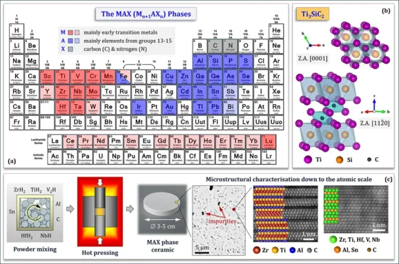
Fig. 1. (a) M, A and X elements in ternary (darker colours) and higher order solid solution (lighter colours) MAX phases. (b) Atomic arrangements in two zone axes (Z.A.) in the Ti3SiC2 MAX phase. (c) Powder metallurgical processing of MAX phase ceramics followed by multiscale microstructural characterisation. High-angle annular dark-field (HAADF) STEM images of MAX phase solid solutions in the (Zr,Ti)-Al-C (left) and (Zr,Ti,Hf,V,Nb)-(Al,Sn)-C (right) systems.
Application-driven material design & material-specific processing
H2020 IL TROVATORE targets the optimisation and validation of select ATF cladding material concepts in industrially relevant conditions, i.e., under irradiation in the BR2 test reactor in contact with PWR (pressurised water reactor) water. This section describes the challenges involved in the design and fabrication of nuclear materials, using the MAX phase-coated variant of the coated zirconium-based alloy (zircaloy) ATF cladding material concept as test case. Another variant of the same material concept, the Cr-coated zircaloy, is expected to be deployed to market between 2026 and 2028 by two major PWR fuel vendors, i.e., Framatome and Westinghouse. It is important to note that for ‘exotic’ coating materials, such as the MAX phases, ANMD foresees that material design, processing, and performance assessment begin with bulk materials before producing coatings with the best-performing material to make best use of the available resources. The MAX phases [1] are nanolaminated ternary carbides and nitrides described by the Mn+1AXn general stoichiometry, where M is an early transition metal, A is an A-group element (mainly, groups 11-16) in the periodic table, X is C or N, and n is usually equal to 1, 2 or 3 (Fig. 1a). The MAX phases are promising materials for nuclear applications due to their remarkable radiation tolerance, esp. at temperatures > 600°C, making them ideal candidates for nuclear systems with high nominal operation temperatures, such as Gen-IV lead-cooled fast reactors (LFRs). Using MAX phase ceramics in Gen-II/III LWRs, however, requires sophisticated materials engineering due to their non-ideal radiation response at LWR-relevant operation temperatures (i.e., 280-340°C). MAX phase ceramics designed for nuclear applications should ideally exhibit good compatibility with the coolant, high phase purity, strong textures, and fine-grained microstructures. High phase purity is needed to prevent failure due to differential swelling, which damages phase mixtures because each phase swells differently under irradiation, causing irreconcilable stresses at grain boundaries (GBs) that lead to the formation and propagation of intergranular cracks. Texture (i.e., grain alignment along specific crystallographic directions) aims at preventing failure of MAX phase ceramics due to anisotropic swelling of the hexagonal MAX phases (space group P63/mmc), which expand along the c-axis and contract along the a-axis under irradiation. Figure 1b depicts two different zone axes (i.e., crystallographic directions) in the crystal structure of an extensively studied member of the MAX phase family, i.e., Ti3SiC2. Grain refinement is pursued because GBs are known to act as ‘sinks’ for irradiation-induced defects in MAX phase ceramics [2]. MAX phase ceramics with high phase purity can be fabricated via powder metallurgical routes involving pressure-assisted densification of powder compacts, e.g., hot pressing (Fig. 1c). The cornerstones of the experimental synthesis of such ceramics are (a) the judicious design of double solid solution MAX phases (i.e., solid solutions on both M- and A-sites of the MAX phase), such as (Zr,Nb)2(Al,Sn)C [3] and (Zr,Ti)2(Al,Sn)C [4], and (b) the use of early transition metal hydride powders instead of elemental powders [5]. The design of double solid solution MAX phases considers the relative atomic radii of the M & A elements to minimise crystal lattice distortions capable of destabilising the MAX phase compound and yielding large fractions of undesirable phases, such as binary carbides and intermetallics (IMCs). A recent trend in the design of MAX phases with exceptional radiation tolerance aims at fabricating solid solutions with high chemical complexity, such as (Zr,Ti,Hf,V,Nb)2(Al,Sn)C [6]. Chemical complexity – also explored in high-entropy alloys [7] – is held accountable for a reduced mobility of radiation-induced defects, a high density of defects ‘sinks’ or defect recombination centres, and a reduced tendency for defect accumulation that typically leads to void swelling. Based on the above, nuclear materials design can start at the atomic scale, demonstrating the sophistication in materials engineering that might be needed if a specific material (e.g., the MAX phases) calls for it. Material fabrication is invariably followed by multiscale microstructural characterisation (Fig. 1c), starting with commonly available analytical techniques, such as light optical microscopy (LOM) and scanning electron microscopy (SEM), and gradually proceeding to analytical techniques with high spatial resolution, such as scanning transmission electron microscopy (STEM) and atom probe tomography (APT).
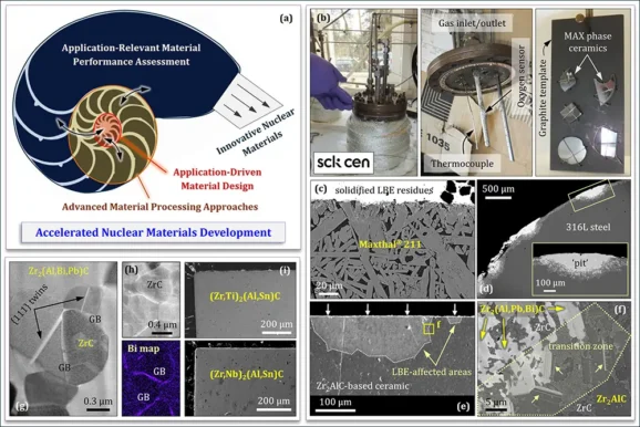
Fig. 2. (a) ANMD entails communication between application-driven material design, material processing, and material performance assessment. (b) Setup used to expose MAX phases to static HLMs (Pb, LBE). A graphite template maintains the MAX phases immersed in the HLMs. (c) Maxthal® 211 (nominally, Ti2AlC) exposed to liquid LBE (500°C, 3500 h, CO < 10-9 mass%) shows no HLM attack. (d) Structural 316L stainless steel exposed to liquid LBE (500°C, 3282 h, CO< 10-8 mass%) shows severe LBE dissolution attack with deep pits. (e) Zr2AlC-based ceramic exposed to liquid LBE (500°C, 1000 h, CO≤ 2.2×10⁻¹⁰ mass%) shows local interaction with LBE. (f) Transition zone between Zr2AlC and LBE-affected Zr2(Al,Pb,Bi)C MAX phase solid solution. (g-h) GBs and {111} twins are preferred paths of LBE ingress into otherwise unaffected ZrC grain clusters. (i) (Zr,Ti)2(Al,Sn)C and (Zr,Nb)2(Al,Sn)C MAX phase solid solutions exposed to liquid Pb (500°C, 2000 h, CO < 10-10 mass%) show no HLM attack.
Application-relevant material performance assessment
The cross-cutting character of R&D activities in H2020 IL TROVATORE permitted the design of MAX phases for Gen-IV LFRs, which are cooled by heavy liquid metals (HLMs) such as liquid lead (Pb) and lead-bismuth eutectic (LBE). Due to the inherent corrosiveness of HLMs, the chemical compatibility of candidate materials with HLMs must be assessed under various conditions. For this purpose, MAX phase ceramics were exposed to liquid Pb/LBE in dedicated autoclaves (Fig. 2b); during testing, both temperature and concentration of dissolved oxygen in the HLM (CO) were monitored using a thermocouple and an electrochemical oxygen sensor, respectively [8,9]. The MAX phase samples were kept immersed in the HLM bath by attaching them on a graphite template (Fig. 2b), otherwise they would float on the HLM surface [8]. Most of the MAX phases showed excellent compatibility (i.e., no interaction) with liquid LBE (e.g., Maxthal® 211; Fig. 2c), except from the local LBE interaction observed in Zr2AlC (Figs. 2e-f). Contrary to the destructive LBE dissolution attack of 316L stainless steels tested under similar conditions (Fig. 2d) [10], the LBE-affected areas in Zr2AlC transformed (non-destructively) in situ into the Zr2(Al,Pb,Bi)C MAX phase solid solution due to the partial substitution of Al on the A-site by Pb and Bi [9]. Phase purity of MAX phase ceramics designed for nuclear applications is also important vis-à-vis coolant compatibility. Evidence of this statement is provided in Fig. 2g, where {111} twin planes in the ‘parasitic’ ZrC phase act as paths of preferential LBE ingress into the tested Zr2AlC-based ceramic. Clusters of (undesirable) ZrC grains form during the powder metallurgical processing of Zr2AlC [11]; as such, ZrC grains are impervious to LBE attack, however, their GBs offer paths of LBE ingress in the Zr2AlC-based ceramic (Fig. 2h). Figure 2i shows that judicious material engineering down to the atomic scale can produce liquid metal corrosion-resistant MAX phase solid solutions, such as the (Zr,Ti)2(Al,Sn)C [4] and (Zr,Nb)2(Al,Sn)C [3] tested in liquid Pb/LBE.
Characterisation of the fabricated materials is not limited to microstructural analysis (Fig. 1c) but also entails mechanical property determination. Figure 3a is a STEM image of the area under an indentation in a Zr2AlC grain, showing the formation of a large (>150 μm) delamination crack growing parallel to the MAX phase basal planes. Indentation can be used to determine hardness, stiffness (Young’s modulus), and fracture toughness of materials. Figure 3b is a high-resolution STEM image of the delamination crack termination, showing the presence of an atomically sharp crack. As dictated by fracture mechanics, a region of plasticity is established ahead of the crack tip when the stresses exceed the material’s yield strength [12]. Fast Fourier Transformation (FFT) processing of STEM images ahead of the crack tip identified the exact location of the crack tip and confirmed the presence of an edge dislocation indicative of local plasticity (Figs. 3c-d). Such findings, only possible by the advent of very powerful TEMs (Fig. 3f), provide invaluable insights into the deformability of complex materials such as the MAX phases. The same indentation study shed additional light into the deformation of Zr2AlC by kinking [13].

Fig. 3. (a) STEM image of the area under an indentation in Zr2AlC showing the formation of a delamination crack. (b) At its termination, the delamination crack becomes atomically sharp. (c) The crack tip is located inside the white circle, whereas an edge dislocation is present inside the yellow circle. (d) FFT filtering of Fig. 3c reveals the exact locations of crack tip and edge dislocation. (e) The MIAMI-2 facility used for in situ ion irradiation in the TEM. (f) The double Cs-corrected FEI Titan3 60-300 used for PIE of ion-irradiated materials. (g) Differential swelling in a Zr2AlC-based ceramic irradiated with 6 keV He+ to 4 dpa at 600°C. (h) Differential swelling in a Cr2AlC ceramic irradiated with 6 keV He+ to 7.5 dpa at 600°C. A brittle crack (arrow) is visible in Cr7C₃. (i-j) Zr2AlC irradiated with 6 keV He+ to 7.5 dpa at 600°C. He platelets (stars) form parallel to the basal planes in Zr2AlC, causing local buckling of the crystal lattice.
Another important aspect of the performance assessment of candidate nuclear materials is their radiation response. In this respect, sophisticated analytical tools, such as the MIAMI-2 facility (Fig. 3e) used for in situ ion irradiation in the TEM, become real assets to the development of innovative nuclear materials. Apart from MIAMI-2 [14], only a handful of similar facilities in the world are able to conduct in situ ion irradiations in the TEM, thus permitting the continuous monitoring of the evolution of radiation-induced damage. Such experiments are more efficient in unravelling the material degradation process under irradiation as compared to the standard PIE approach that investigates damage only at the maximum dose. MIAMI-2 tests performed on Zr2AlC-based (Fig. 3g) and Cr2AlC-based (Fig. 3h) MAX phase ceramics at 600°C using 6 keV He+ to 4 dpa and 7.5 dpa, respectively, demonstrate the importance of phase purity for material stability under irradiation. For example, the Zr2AlC ceramic (67 wt.% Zr2AlC, 33 wt.% ZrC & Zr-Al IMC [11]) showed intergranular crack formation and propagation due to differential swelling. Despite the high phase purity of the Cr2AlC ceramic (>98 wt.% Cr2AlC), evidence of differential swelling was also found in triple junctions filled with ‘parasitic’ phases (i.e., Cr-Al IMC & Cr7C3). Interestingly, defects such as {111} twins in ZrC (arrows in Fig. 3g) accumulated helium (He+), leading to crack nucleation and underlying the importance of phase purity. Moreover, the irradiation-induced defects were phase-specific, i.e., large equiaxed He bubbles formed in Zr-Al & Cr-Al IMCs, small equiaxed He bubbles formed in Cr2AlC, whilst He platelets formed parallel to the basal planes in Zr2AlC, causing local ™l buckling of the crystal lattice (Figs. 3i-j). Studies of the radiation response of MAX phase solid solutions, such as (Ti,Zr)2(Al,Sn)C, are also essential [15].
A stepping stone to the successful implementation of the ANMD approach is the development of test setups able to recreate in-reactor material service conditions. This idea was the incentive behind the development of the IAC (irradiation-accelerated corrosion) cell employed to perform synergistic proton irradiation/aqueous corrosion tests on materials in contact with (slowly) flowing water of controlled chemistry [16]. In the framework of the I-NERI US/EURATOM PERSEUS project (focusing on PIE activities), an IAC test was conducted on CVD (chemical vapor deposited) SiC, typically used as outer protective coating of CVI (chemical vapor infiltrated) SiC/SiC composite ATF claddings. The as-fabricated CVD SiC consisted of columnar SiC grains with high density of stacking faults (SFs) that appear as parallel fine lines in the HAADF STEM images of Fig. 4c. The (polished) disc-shaped CVD SiC sample (ø3 mm, 48 μm-thick) was tested using 5.4 MeV protons (p+), at 320°C, for 48 h, in PWR water with 3 ppm H2. After testing, the CVD SiC disc appeared perforated (Fig. 4b), and three areas were identified on its surface (inset of Fig. 4a) due to changes in the SiC degradation mechanism between area 1 (proton irradiation & water radiolysis), area 2 (water radiolysis), and area 3 (aqueous corrosion). Further STEM analysis revealed the preferential attack of GBs & SFs by water radiolysis species such as H+ (Fig. 4d); these findings agree with ab initio molecular dynamics simulations of SiC aqueous corrosion effects, which showed that the scission of Si-C bonds by hydrogen species is an important step in the SiC hydrothermal degradation process [17].
HORIZON SCORPION aims at optimising the performance of SiC/SiC composite ATF cladding materials for Gen-II/III LWRs. SCORPION employs two approaches to improve the SiC coolant compatibility: (a) the development of protective coatings preventing the formation of silica (SiO2), as it jeopardises the reliable performance of SiC in water and steam, and (b) the GB engineering of SiC with compounds that exhibit excellent stability in water and steam. Figure 4e shows SEM images of pressurelessly sintered yttrium aluminium garnet (YAG) and spark plasma sintered SiC GB engineered with YAG. YAG (Y3Al5O12) is a candidate SiC coating material with excellent water/steam compatibility, which has already been tested in the IAC cell at identical conditions as CVD SiC, i.e., 5.4 MeV p+, 320°C, 48 h, PWR with 3 ppm H2. Figure 4f shows that the tested YAG disc (ø3 mm, 50 μm-thick) exhibited a good overall performance with mild GB etching in areas 1 & 2 and dissolution of parasitic alumina (Al2O3) in areas 1-3.
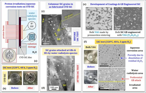
Fig. 4. (a) The IAC cell used for synergistic proton irradiation/aqueous corrosion tests. The inset schematic shows three areas on the tested sample surface due to variations in degradation mechanism. (b) A CVD SiC disc tested in the IAC cell (5.4 MeV p+, 320°C, 48 h, PWR water with 3 ppm H2) appeared perforated (central hole). (c) HAADF STEM images of as-fabricated CVD SiC showing columnar SiC grains with a high density of SFs. (d) During IAC testing, CVD SiC was preferentially attacked at GBs & SFs. (e) SEM images of bulk YAG (left) and bulk SiC GB engineered with YAG (right). (f) An YAG disc tested in the IAC cell at identical conditions as the CVD SiC disc remained integral. Degradation was limited to mild GB etching and pore formation due to the dissolution of residual Al2O3.
The importance of international collaborations
Global quests, such as the expedited development of ATF cladding materials, benefit greatly from international collaborations, such as H2020 IL TROVATORE, HORIZON SCORPION, and I-NERI PERSEUS, not only for the exchange of data and know-how, but also for the sharing of unique resources needed for material development (e.g., MIAMI-2, IAC cell, etc.) and material validation (e.g., test reactors, state-of-the-art analytical tools needed for PIE, etc.). Crucial to the success of such collaborations is to complete key R&D activities such as the BR2 irradiation campaign in H2020 IL TROVATORE, the PIE at JRC Karlsruhe in HORIZON SCORPION, etc. Even though such R&D activities are essential for ultimate materials validation, the scarcity of test reactors and laboratories capable of performing state-of-the-art PIE analyses is a bottleneck in nuclear materials innovation on global scale.
Further information
HORIZON SCORPION website: projectscorpion.eu
H2020 IL TROVATORE website: iltrovatore-h2020.eu

Prof Dr Konstantina Lambrinou is Professor of Advanced Materials at the School of Computing and Engineering, University of Huddersfield, UK. Her research activities focus on the accelerated development of nuclear materials, including ATFs. Prof Lambrinou is the principal investigator (PI) of HORIZON SCORPION (Grant Agreement No 101059511) and H2020 IL TROVATORE (Grant Agreement No 740415), the European lead of I-NERI PERSEUS, and the technical lead of a Westinghouse GAIN program on the Cr-coated ATF cladding (No NE-23-31246).

Mr Robert L. Oelrich is the Nuclear Engineering Group lead within the National Security Directorate at Pacific Northwest National Laboratory (PNNL). The Nuclear Engineering Group serves multiple internal and external projects on nuclear materials performance, including ATFs. Mr Oelrich is also the Chief Engineer for the Tritium Technology Program that supports select activities in US Defence Programs, the US lead of I-NERI PERSEUS, and the PI of a Westinghouse GAIN program on the Cr-coated ATF cladding (No NE-23-31246).
[email protected], PNNL website: www.pnnl.gov
References
[1] N. Goossens, B. Tunca, T. Lapauw, K. Lambrinou, J. Vleugels, MAX phases, structure, processing, and properties, Encyclopedia of Materials: Technical Ceramics and Glasses 2 (2021) 182-199
[2] D.J. Tallman, L. He, J. Gan, E.N. Caspi, E.N. Hoffman, M.W. Barsoum, Effects of neutron irradiation of Ti3SiC2 and Ti3AlC2 in the 120-1085°C temperature range, Journal of Nuclear Materials 484 (2017) 120-134
[3] T. Lapauw, B. Tunca, D. Potashnikov, A. Pesach, O. Ozeri, J. Vleugels, K. Lambrinou, The double solid solution (Zr,Nb)2(Al,Sn)C MAX phase: a steric stability approach, Scientific Reports 8 (2018) 12801
[4] B. Tunca, T. Lapauw, R. Delville, D.R. Neuville, L. Hennet, D. Thiaudière, T. Ouisse, J. Hadermann, J. Vleugels, K. Lambrinou, Synthesis and characterisation of double solid solution (Zr,Ti)2(Al,Sn)C MAX phase ceramics, Inorganic Chemistry 58 (2019) 6669-6683
[5] N. Goossens, T. Lapauw, K. Lambrinou, J. Vleugels, Synthesis of MAX phase-based ceramics from early transition metal hydride powders, Journal of the European Ceramic Society 42 (2022) 7389-7402
[6] B. Tunca, S. Huang, N. Goossens, K. Lambrinou, J. Vleugels, Chemically complex double solid solution MAX phase-based ceramics in the (Ti,Zr,Hf,V,Nb)-(Al,Sn)-C system, Materials Research Letters 10 (2022) 52-61
[7] C. Lu, L. Niu, N. Chen, K. Jin, T. Yang, P. Xiu, Y. Zhang, F. Gao, H. Bei, S. Shi, I.M. Robertson, W.J. Weber, L. Wang, Enhancing radiation tolerance by controlling defect mobility and migration pathways in multicomponent single-phase alloys, Nature Communications 7 (2016) 13564
[8] T. Lapauw, B. Tunca, J. Joris, A. Jianu, R. Fetzer, A. Weisenburger, J. Vleugels, K. Lambrinou, Interaction of Mn+1AXn phases with oxygen-poor, statis and fast-flowing liquid lead-bismuth eutectic, Journal of Nuclear Materials 520 (2019) 258-272
[9] B. Tunca, T. Lapauw, C. Callaert, J. Hadermann, R. Delville, E.N. Caspi, M. Dahlqvist, J. Rosén, A. Marshal, K.G. Pradeep, J.M. Schneider, J. Vleugels, K. Lambrinou, Compatibility of Zr2AlC MAX phase-based ceramics with oxygen-poor, static liquid lead-bismuth eutectic, Corrosion Science 171 (2020) 108704
[10] K. Lambrinou, E. Charalampopoulou, T. Van der Donck, R. Delville, D. Schryvers, Dissolution corrosion of 316L austenitic stainless steels in contact with static liquid lead-bismuth eutectic (LBE) at 500°C, Journal of Nuclear Materials 490 (2017) 9-27
[11] T. Lapauw, K. Lambrinou, T. Cabioc’h, J. Halim, J. Lu, A. Pesach, O. Rivin, O. Ozeri, E.N. Caspi, L. Hultman, P. Eklund, J. Rosén, M.W. Barsoum, J. Vleugels, Synthesis of the new MAX phase Zr2AlC, Journal of the European Ceramic Society 36 (2016) 1847-1853
[12] K. Lambrinou, Factors affecting the bulk embrittlement of Pb-free solder joints, Chapter 2 in the ELFNET Handbook on Failure Mechanisms & Testing Methods for Lead-Free Solder Interconnects, G. Grossmann and Ch. Zardini (Eds.), 2011, pp. 19-63, Springer-Verlag London Ltd
[13] G. Plummer, H. Rathod, A. Srivastava, M. Radovic, T. Ouisse, M. Yildizhan, P.O.Å. Persson, K. Lambrinou, M.W. Barsoum, G.J. Tucker, On the origin of kinking in layered crystalline solids, Materials Today 43 (2021) 45-52
[14] G. Greaves, A.H. Mir, R.W. Harrison, M.A. Tunes, S.E. Donnelly, J.A. Hinks, New Microscope and Ion Accelerators for Materials Investigations (MIAMI-2) system at the University of Huddersfield, Nuclear Instruments and Methods in Physics Research Section A: Accelerators, Spectrometers, Detectors and Associated Equipment 931 (2019) 37-43
[15] B. Tunca, G. Greaves, J.A. Hinks, P.O.Å. Persson, J. Vleugels, K. Lambrinou, In situ He+ irradiation of the double solid solution (Ti0.5,Zr0.5)2(Al0.5,Sn0.5)C MAX phase: Defect evolution in the 350-800°C temperature range, Acta Materialia 206 (2021) 116606
[16] S.S. Raiman, A. Flick, O. Toader, P. Wang, N.A. Samad, Z. Jiao, G.S. Was, A facility for studying irradiation accelerated corrosion in high temperature water, Journal of Nuclear Materials 451 (2014) 40-47
[17] J. Xi, C. Liu, D. Morgan, I. Szlufarska, Deciphering water-solid reactions during hydrothermal corrosion of SiC, Acta Materialia 209 (2021) 116803
Acknowledgments: H2020 IL TROVATORE & HORIZON SCORPION received funding from the Euratom Research and Training Programme 2014-2018 under Grant Agreement No 740415 & the Euratom Research and Training Programme 2021-2025 under Grant Agreement No 101059511, respectively. The IAC test on CVD SiC was funded by US-DOE, Office of Nuclear Energy under DOE Idaho Operations Office Contract No DE-AC07-051D14517, whereas the post-test analysis was co-funded by Westinghouse, PNNL, and H2020 IL TROVATORE.